Still too light at night for deep sky stuff, but as the Sun has been shining almost every day for the last few weeks, I’ve been able to continue concentrating on some Solar observing work.
My previous attempts at drawing Sunspot detail were OK, but positioning isn’t particularly accurate. I remember seeing a Solar Projection box being used at the Winchester Weekend a few years ago and was impressed at how simple it would be to construct and how bright the projected image was.
A few days ago I came across a Google scan of a Springer book on Solar observing, which has a simple design for such a box. Also given were a couple of paragraphs on how to determine which eyepiece to use as well how to calculate the eyepiece to projection screen distance.

The first job was to work out how long to make the box. The easiest way was to stick an eyepiece into the diagonal and project the image onto a clipboard. I tried my useless 26mm Meade Plossl, but it wouldn’t focus an image anything closer than about 1.5 metres. The only other eyepiece I was willing to risk melting was a 10mm Meade Plossl – an eyepiece I hardly ever use. Once fitted, this gave me a 152mm diameter image -in sharp focus, at 400mm from the body of the diagonal.
I did have to allow for the seasonal changes in disk diameter and found at 400mm , I could move the eyepiece in or out of the diagonal to allow for the take up of the 155mm, down to a 149mm disk diameter and still project the image to within the confines of a 152mm circle. This is the standard diameter used by Solar Observers

A few bits of Balsawood, some Cyno and a couple of days work and Bingo, this is it. The box slides over the eyepiece end of the diagonal. There is a flat there which provides a reasonably amount of rigidity. At the moment, I’m tying it on with string, but thin elastic shock cord should do the trick on the finished version.
The first flaw in the design, is now the box is orientated onto the diagonal. The viewing port is facing towards the Sun and not away from it. The eyepiece screw clearance slot was cut in the wrong side, but rather than cut another on the other side, I think I will just blank off the current viewing slot, and just cut another one on the opposite side of the box.
In the base of the box, I have glued in some white Plasticard. This is there to allow for a brighter view for multiple observers at star parties. For Sun disk drawings, I will overlay paper with a printed 152mm circle onto the Plasticard. This can be held down using a Bulldog clip.
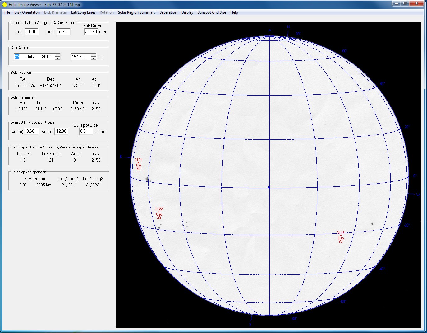
So what of ‘First Light’ and an initial test drawing. With a lack of Sunspots over the last few days I wasn’t hopeful of being able to draw anything, but Sunspots 2119, 2121 and 2122 came to my rescue.

Sunspot numbers from the SOHO website today…..

….and my aligned drawing.
Before plotting the Sunspots, I had to mark the East/West orientation so the image can be aligned correctly when scanned into the Helio viewer Software This is dome by turning off the scope tracking, marking the position of a prominent spot and marking where it ends up after a few minutes . The line between the two marks is your East/West track. I then used a softish pencil and marked the positions of the few Sunspots that were visible.
The finished drawing was then scanned into Photoshop and rotated using the ruler tool , so that the East/West line was aligned horizontally. I then had to black fill outside of the 152 circle on the paper, so when the scanned image is loaded into Helio viewer, the software is able to detect the size of the image and scale all the overlay data correctly. The Sunspot data overlay is imported as text files for that day, from the Solar Region Summary pages on the NOAA website

As you can see in the above image, the data overlay doesn’t match my drawing particularly well.

To check why, I download an image from the SOHO website of the Sun taken at the same time I made my drawing. Loading each into its own layer, sizing them to the same diameter and rotating them, the Sunspots aligned perfectly, so no problem there.

It looks like I didn’t take enough care when aligning the East/West drift line, which is why I had to rotate my image to match the SOHO one. While this will bring spots into rotational alignment they will all still be out laterally East/West, so I’m not sure why this should be. I can get a good match if the image is rotated and the date is advanced by exactly one day.
I will be a little more careful in ensuring the alignment of the drawing next time, but need to check the SRS data is being applied correctly in Helioviewer.